
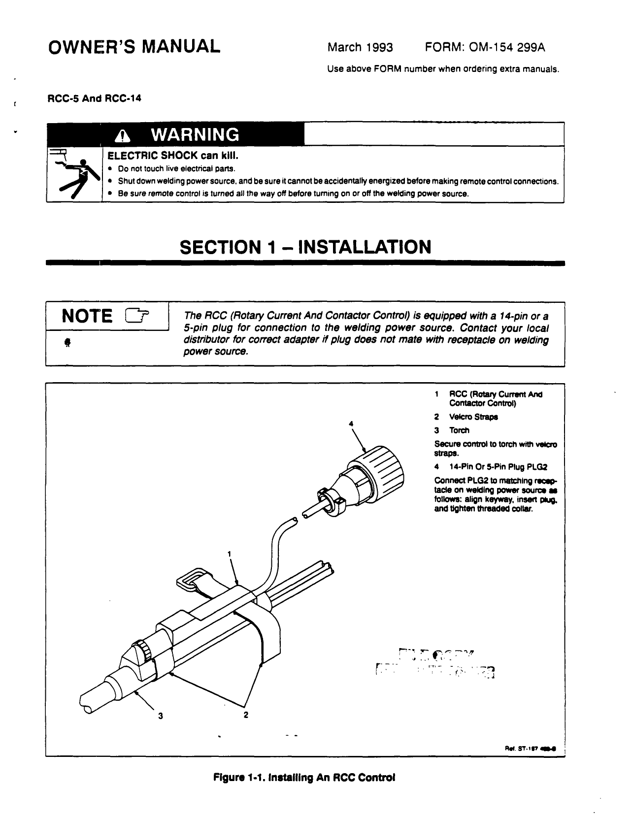
Miller Remote Wiring Diagram
Get free help, tips & support from top experts on s52e miller related issues. For information on other quality miller products,.
Miller Remote Wiring Diagram Wiring Diagram and Schematic
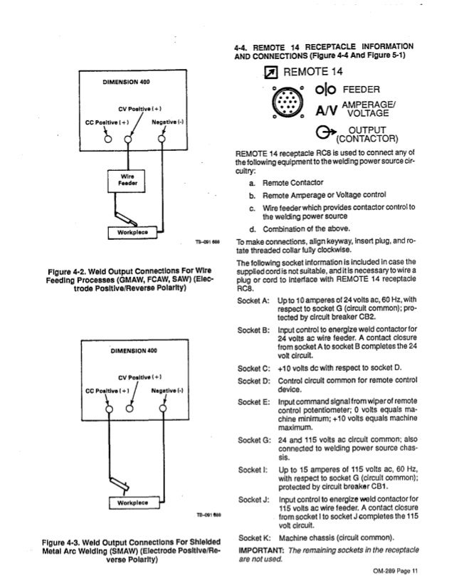
Complete current or voltage control brings 120 v of gfci power to work area in a single cord, 125 ft.
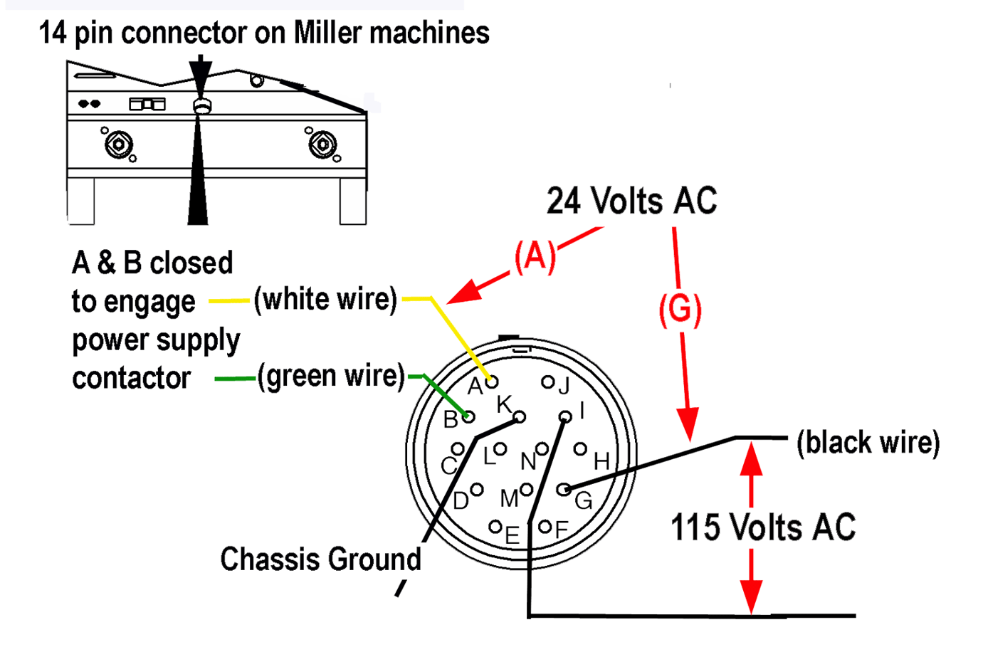
Miller remote wiring diagram. Millermatic plus 30a spoolgun(canada) this the wiring diagram to convert the 30a 8 wires 10 pin connector plug to fit the mtss. I have the wiring diagram for the intelliweld. With a meter on ac voltage check between pins a & b.
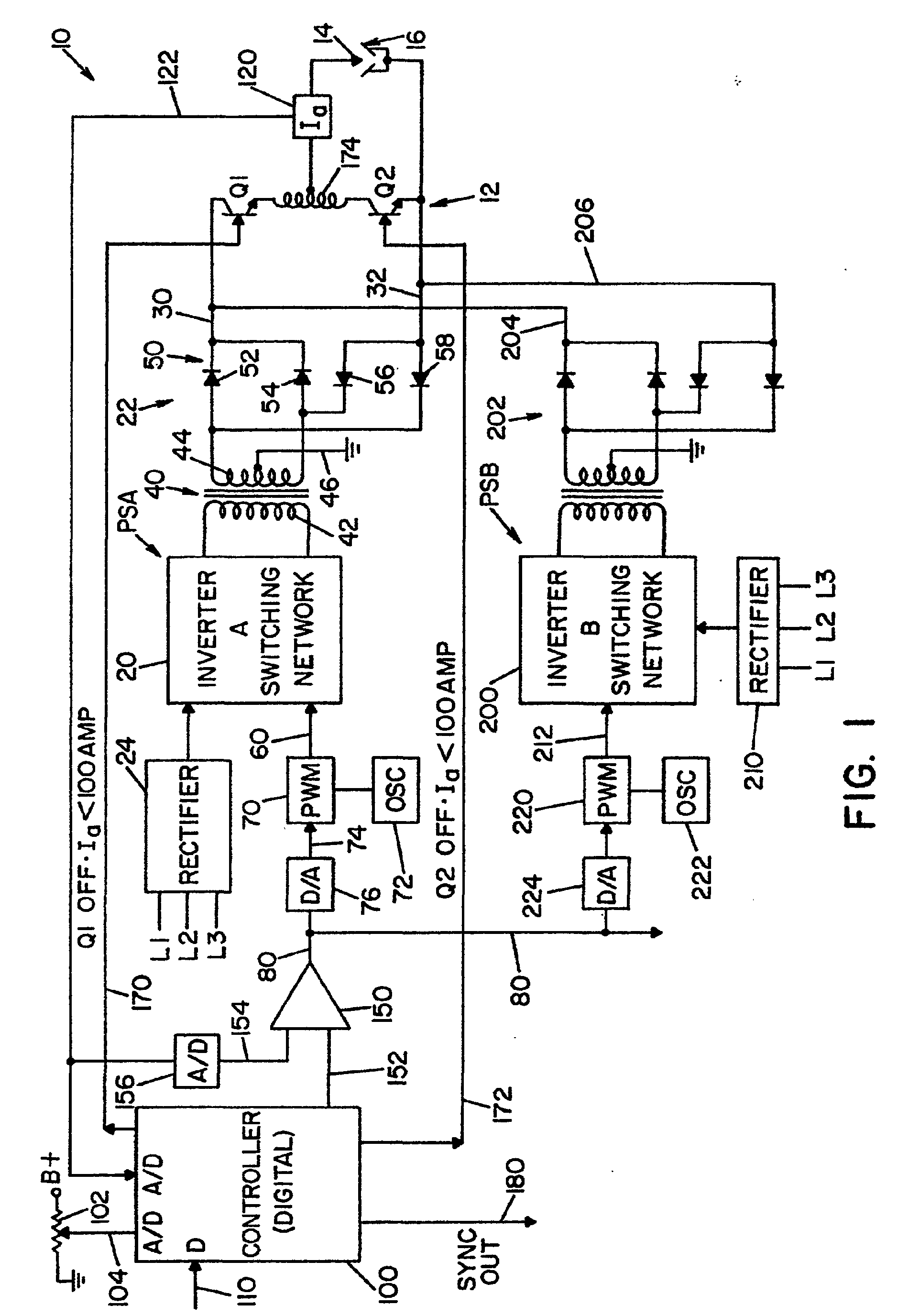
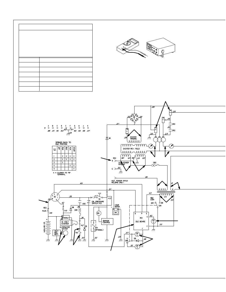
Miller 14 pin wiring diagram images, similar and related articles aggregated throughout the internet. Welding generator circuit diagram and/or instruction manual. Remote amperage or voltage control for welding power source with output always on 16.
Diagramweb.net cool welder plug wiring diagram contemporary electrical circuit img source: Normally of the machine has a pilot light that lights when the machine is on. Miller electric manufactures a full line of welders and welding related equipment.
Box 1079 appleton, wi 54912 usa. Wireless remote foot control miller electric mfg. Older hobart hefty wire feeder hyperthrem 600 maxstar 150s(such a cute welder) had and sold.
I was going to try to hook a 14 pin up to it as well. Consult miller electric mfg.'s entire dialarc® 250 ac/dc catalogue on directindustry. Bearing in mind a pain to remove, replace or fix the wiring in an automobile, having an accurate and detailed miller remote wiring diagram is.
Llc an itw welding company 1635 west spencer street p.o. Ssc remote foot pedal for miller tig welders 5pin plug rfcs 5 img source: The results should be as follows, with a smooth change in output as the pedal is pressed.
You can buy the cable to adapt the sm 1 to a 10 pin connector from miller4less, but i figure why pay $60 if i have the 10 pin connectors. Wire welding, the wire, wire reel, drive roll housing,. Only for esabfeed with m13 panel.
I see from the official factory diagram that there are 2 x.1uf ceramic caps also. Miller makes no warranty, express or implied, as to the finished products manufactured or supplied by another manufacturer and supplied by miller to purchaser, including, but not limitedto, anyvehicleto whicha millerproduct maybe affixedor anyaccessories or wire rope, and miller expressly disclaims any implied warranties. Using a multimeter on the ohms setting, check pins c, d, and e at the end of the plug (with the pedal unplugged).
I could just wire the 10 pin to the sm 1 without too much trouble. Need wiring schematic for miller wire feed welder looking for spool gun. Section 7 − electrical diagrams 21.
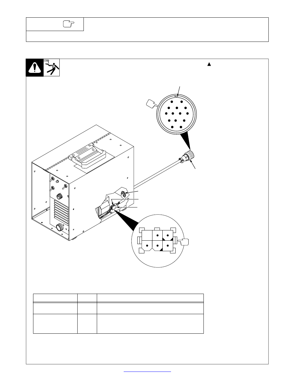
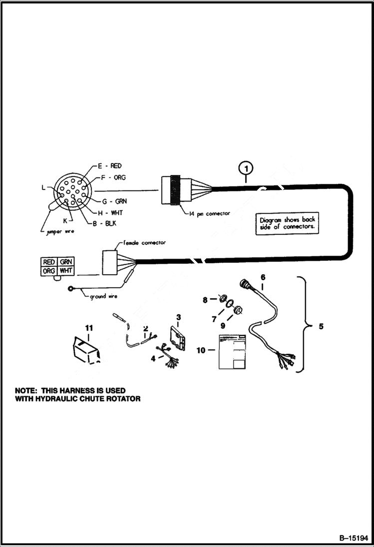
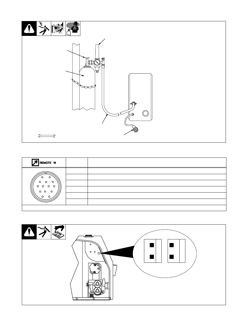
Miller style 14 pin receptacle diagram. How to identify the 14 pin connector on your machine. Use remote output control if present on unit.
These schematics were created by tracing out individual circuit paths on the pcb's for the remote controls and the main logic board inside the welder unit. A miller group ltd., company p.o. Could be the welder, the gun motor, the wiring, ect.
Remote amperage control for welding power source without remote control switch ref. Note that the control requires a constant source of power with the red (hot) and white Miller makes no warranty, express or implied, as to the finished products manufactured or supplied by another manufacturer and supplied by miller to purchaser, including, but not limited to, any vehicle to which a miller product may be affixed or any accessories or wire rope, and miller expressly disclaimsany implied.
(for miller® welders) wiring diagram and test instructions how to check the potentiometer: Mig (gmaw) for product information, owner's manual translations, and more, visit www.millerwelds.com. Diagramweb.net welder wiring diagram in addition to mig welder wiring diagram img source:
Ive had one for a few years, a ya!buddy!! Matic parts that come in contact with the welding wire including nozzles and nozzle insulators where failure does not result from. Does anyone have the actual wiring diagram for a miller 30a spool gun?
With the machine turned on (the cooling fan may or may not run with the machine on).
Lincoln Sa 200 Parts Diagram Wiring Diagram

miller 14 pin info page

Miller Bobcat 250 Wiring Schematic Wiring Diagram
Miller bobcat 250 service manual
Miller 14 Pin Connector Wiring Diagram Ekerekizul
Miller 14 Pin Connector Wiring Diagram Wiring Diagram

Miller 115/240 Wiring Diagram

Honeywell Limit Switch Wiring Diagram Free Wiring Diagram
Miller 14 Pin Remote Wiring Diagram Wiring Diagram and
Miller Bobcat 250 Wiring Schematic Wiring Diagram
19 Images Miller 14 Pin Connector Wiring Diagram

Safgard Low Water Cut Off Wiring Diagram Download

australia ceiling fan installation The Biggest Home
Aquatherm Wiring Diagram
Miller Remote Wiring Diagram Style Guru Fashion, Glitz

Miller Remote Wiring Diagram Style Guru Fashion, Glitz
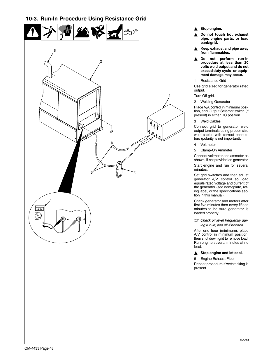
3. runin procedure using resistance grid Miller

Miller 14 Pin Connector Wiring Diagram Wiring Site Resource
Patent US7319206 Method and apparatus for receiving a

